Research on Optical Module in FPGA Optical Fiber Transmission Circuit
The optical fiber data transmission circuit is divided into five parts: optical fiber transmission, photoelectric signal conversion, signal acquisition and transmission, data processing, and data transmission. Optical signals are transmitted between measurement systems through optical fibers; photoelectric signal conversion is performed by optical interface adapters and optical modules to convert signals into photoelectric and electro-optical signals; signal acquisition and transmission are sent through high-speed serial transceivers to send data into FIFO or dual-port RAM cache; Data processing interacts through the asynchronous communication EMIF interface of FPGA+DSP structure; data transmission communicates data, instructions, etc. with the host computer or other testing equipment through Gigabit Ethernet or RS-422 interface. The optical module part will be introduced in detail below.
Optical Module Device Selection
The performance of the optical module affects the high-speed transmission capability of the circuit. The selection of the optical module model should refer to the following elements:
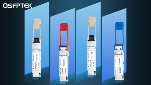
1) Package form: The assembly requirements of optical modules determine the package form. For industry specifications and compatibility, the package is uniformly regulated by the MSA organization. Common optical module packages: 1x9, SFF, SFP, XFP, QSFP28, etc.
2) Interface type: It needs to be matched with optical fiber interface, common optical module interface: FC type, LC type, SC type, ST type, MT type.
3) Transmission rate: Rate is one of the core indicators of optical communication. The maximum rate is determined by different types of optical devices and modulation techniques, from the initial 155Mb/s to the current 400Gb/s and 800Gb/s.
4) Transmission distance: Distance is one of the core indicators of optical communication. There are three types: short distance (2km and below), medium distance (10-20km), and long distance (30km and above). The distance is limited by the band loss and dispersion characteristics.
5) Center wavelength: The working wavelength is a range, and the common center wavelengths are 850nm, 1310nm, and 1550nm. Among them, 850nm wavelength has low cost and short transmission distance, and can only transmit 500m; 1310nm wavelength has large loss and small dispersion, and the transmission distance is less than 40km; 1550nm wavelength has low loss and large dispersion, and the transmission distance is greater than 40km.
6) Optical fiber type: single-mode optical fiber has a yellow appearance, and multi-mode optical fiber has an orange-red appearance.
7) Working environment: There are two power supply voltages: 3.3V and 5V. The industrial grade adapts to the temperature of -40 to 85°C, and the commercial grade adapts to the temperature of 0 to 70°C.
Optical Module Design Principle
The optical module is composed of optoelectronic devices, functional circuits and optical interfaces, etc., and realizes the photoelectric/electro-optical change function. The optoelectronic device consists of two parts: receiving and transmitting. The receiving part completes the photoelectric conversion, and the transmitting part completes the electro-optical conversion. The transmitting part is composed of parallel multi-channel VCSEL array, parallel multi-channel integrated driver chip, and front-end parallel optical components. The input multi-channel parallel high-speed electrical signals are amplified by the internal driver chip and then drive the VCSEL to convert into optical signals and output in parallel through the optical components. The receiving part is composed of parallel multi-channel PD + parallel integrated TIA chip and front-end parallel optical components. When the optical signal arrives, it is converted into a smaller amplitude electrical signal by the multi-channel optical signal detector PD, and then converted into a larger amplitude electrical signal after the limiting amplifier. , and output a warning signal when the input optical power is less than a certain value.
Optical Module Circuit Design
The photoelectric conversion function uses a high-performance LCC48 packaged four-channel parallel optical transceiver integrated module, which has its own transceiver optical power, voltage, and temperature monitoring functions, and transmits information to the FPGA through the I2C protocol. The output port of the module is a round fiber with a certain length, and the tail is an MT optical interface.

